CIV102 Matboard Bridge

Overview: This was our final CIV102 design project, and it involved designing and building a working beam bridge, made out of Matboard and a specific brand of LePage glue. We were required to submit a brief report of our calculations and test the bridge in two ways:
Team: Alan Daniels, Robin Luo, Toluwanimi Odemuyiwa
Process in Action: Once again, the problem definition was already provided by the assignment guidelines, from where we followed the engineering design process:
1. Detailed Design: After the idea generation and analysis of solutions stage – which involved calculating the strength to weight ratio of each design, we picked a trapezoid-shaped beam bridge. This trapezoid-shaped bridge modelled the shape of the moment diagram of a beam bridge, and had more material near the center of the bridge were more force would be experienced under a static load. During this stage, I was responsible for determining the minimum load value that would cause the bridge to fail, and in the end, we designed for 663 N weight, however, we also found that depending on how well we constructed the stiffeners for our bridge, it would fail at 1275 N. I was also responsible for determining the number of diaphragms our bridge would need to maintain its structure under loading. However, when it came time for the actual building of the bridge, we discovered the trapezoid shape wasted material and we were unable to use the required number of diaphragms. In addition, at the point when we were adding stiffeners and structure-supporting elements, we ran out of the maximum amount of glue allowed for the assignment. Thus, we did not account well enough for our usage of material.
2. Testing stage: Our bridge passed the train test; however, failed the loading test at about 700 N, the second lowest value in our tutorial section. Analyzing the bridge afterwards, we discovered we did not have enough diaphragms near the supports; otherwise the bridge was in good shape. This opened my eyes to see the important of paying attention to the tiniest details during design, as even one flaw could destroy a perfectly capable design.
Below are links to the artifacts:
- By passing a train of specified weight over the bridge
- A loading test to see how much load the bridge could support before failure
Team: Alan Daniels, Robin Luo, Toluwanimi Odemuyiwa
Process in Action: Once again, the problem definition was already provided by the assignment guidelines, from where we followed the engineering design process:
1. Detailed Design: After the idea generation and analysis of solutions stage – which involved calculating the strength to weight ratio of each design, we picked a trapezoid-shaped beam bridge. This trapezoid-shaped bridge modelled the shape of the moment diagram of a beam bridge, and had more material near the center of the bridge were more force would be experienced under a static load. During this stage, I was responsible for determining the minimum load value that would cause the bridge to fail, and in the end, we designed for 663 N weight, however, we also found that depending on how well we constructed the stiffeners for our bridge, it would fail at 1275 N. I was also responsible for determining the number of diaphragms our bridge would need to maintain its structure under loading. However, when it came time for the actual building of the bridge, we discovered the trapezoid shape wasted material and we were unable to use the required number of diaphragms. In addition, at the point when we were adding stiffeners and structure-supporting elements, we ran out of the maximum amount of glue allowed for the assignment. Thus, we did not account well enough for our usage of material.
2. Testing stage: Our bridge passed the train test; however, failed the loading test at about 700 N, the second lowest value in our tutorial section. Analyzing the bridge afterwards, we discovered we did not have enough diaphragms near the supports; otherwise the bridge was in good shape. This opened my eyes to see the important of paying attention to the tiniest details during design, as even one flaw could destroy a perfectly capable design.
Below are links to the artifacts:
- Calculations - we used this excel worksheet to determine the optimum dimensions for our bridge, taking into account cost, material, moment of inertia, etc...
Some photos of our handwritten calculations:
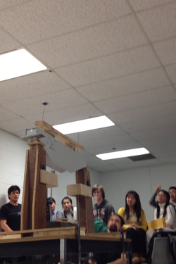
Photos from the Testing of our bridge:
